- 12v
- 5v
- RC Signals
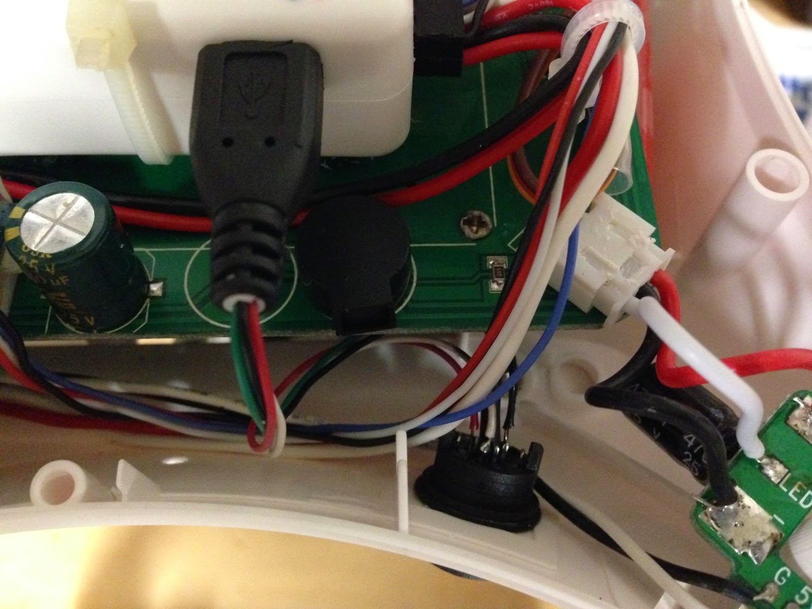
- FC Micro-USB to Mini-USB
I went ahead and loosened Power-Board and removed this PCB. It's not really needed any more and the gimbal blocks it anyway (USB port is inaccessible now). It weighed 9 grams.

It's removal now provides another cavity that might could be used for something. 915mhz radio would fit there if I hadn't just wedged (and foam-taped) it into the other side.
While I could have left this assembly intact, I don't ever see a scenario where I might need to re-install it. So, instead of making my own Micro-end plug, I just cut this one off for re-use. I ohm-out Micro-USB pins and verified wire colors ... they appeared to be standard USB pinouts. Not sure why most websites show variations of USB-Mini pinouts with 1,2,3,x,4 ... I just refer to it like the Micro-port with 1,2,3,4,5.
USB:
I think I will again use Mini-USB as external port due to it's low-insertion force. This one from DigiKey is mostly nylon (weighs about 2 grams) and has a nice insertion snap to it (feels more secure than stock one). On the back of it, I suggest you ohm-out pins so you know where pins1-5 are.

Soldering USB cables proved to require some skill due to thin-delicate scale (high gauge) of parts. I turned the soldering-iron down to 340c, but you still have to be fast and exact. I used helping hands to hold pre-tined wires on tiny pins. Then, use both of my-hands to quickly apply iron and new-final solder. I think it came out pretty good.
You connect Pins 1, 2, 3, and 5 straight thru (not Pin-4 as it is ID-OTG). Make sure they are secured and soldered properly, but never pull or tug on these wires. You can use heat-shrink on all 4 pins if you want, but I think Pin-3 (Green) is only one that requires it, due to proximity position in pin-out.

Passes the "smoke-test" ... works fine with Windows USB device detection and MissionPlanner. This completes the custom mods required to replace the functionality of the removed stock lower-port PCB.

Other possibilities for remote USB include using after market cables run out holes or mounted in body. You could also have something tucked inside battery door. Finally, I think a small hole cut in just the right place would allow a micro-usb cable with a long handle to reach the FC's directly inside.
Here is the current final internal config before installing all the body screws. Telemetry 915mhz radio is back inside. I discovered my ECC has been on this whole time, so I turned it off to see if it might help with Droid-Planner RSSI warnings. Didn't help, so I turned it back on (which is the default).
One X8R antennae had to be moved and is now foam taped to top of X8R now. It's still at 90-degrees to the other back one, but I'll be watching FrSky RSSI.

Wow, I'm glad you did this USB Mod, because I also eliminated that small PCB in favor of internal connections and because my gimbal blocks those connections. Looks like you did all the leg-work (pin-outs, wire colors, mini-USB plug, etc.). I'm just hoping that I'm up for the micro-soldering needed. What exactly is "helping hands" and why no link for those? Otherwise, this is most excellent. THANKS!
ReplyDeleteTry this:
Deletehttp://www.amazon.com/s/ref=as_li_ss_tl?_encoding=UTF8&camp=1789&creative=390957&field-keywords=helping%20hands&linkCode=ur2&tag=quadcopterobo-20&url=search-alias%3Daps&linkId=FGRYEYBLIEUY4LB2