Wednesday, July 30, 2014

FailSafe Setup

I used this document and this video for my FrSky X8R RX radio.

We want no RX pulses to be sent to the FlightController (FC) when the radio signal from the Taranis TX is lost. It's Option #2 in X8R manual-sheet. This way there is no confusion between RX and FC, and FC takes-over (as it should).

MissionPlanner / Initial Setup / Mandatory Hardware / FailSafe

Fail-Safe Options:
  • Battery
    • LowBattery: 0.0v (changes to 6.0v)
    • ReservedMah: 0.0
    • Disabled (Battery Monitoring)
  • Radio
    • Enabled always RTL
    • FS Pwm: 975
  • CGS
    • Disabled (unchecked)

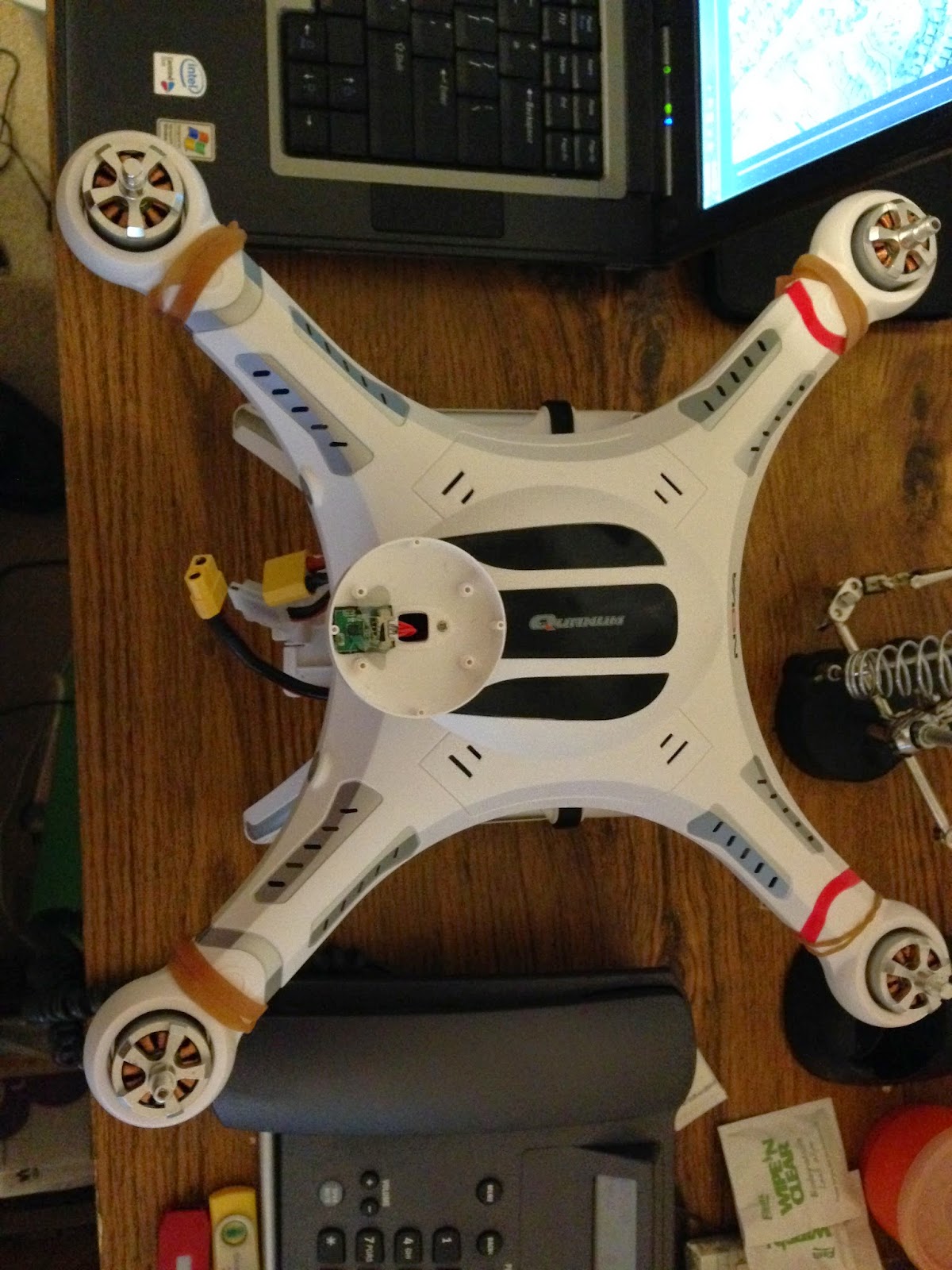
Since my Nova quad has no Power Module, it's my understanding that Low_Battery and Reserved_Mah options are not really being used. Better to disable so that random/floating values don't cause a problem. The Nova's Low-Battery-Alarm (tone and flashing lights) appears to be hardware-based on PowerBoard and permanently fixed around 10.6 volts.

APM2 uses CH-3 to trigger FailSafe. Notice that when radio gets turned off, CH-3 Throttle goes to 900 pwm. Otherwise (when radio is on) it reads like all the others (990-2015). 975 is a good value because it is 15 lower than 990 and 75 higher than 900 (it's recommended that the separation ranges be 10 or more).

Do the test like in the video, and verify that it completes the test and "lands". My FC is inside quad so PROPS MUST BE REMOVED. This also appears to be a good place to test radio operation and stick throws to previously calibrated limits, Also, be sure stick movement is proportional (or linear) through entire range. You should also be able to see if something needs to be reversed (although "Holding by Landing Gear" test below is even better to test for need of channel reversals).

I can't really think of any reason to get back inside at this point. I removed rubber-bands and installed top cover screws and the propellers. Applied a little strip of clear packing-tape to prevent the puck cover from popping-off during flight or hard landing.

With props installed, I did a little "Holding by Landing Gear" test. It was just me carefully holding it by landing gear (use a helper if available). Make sure it pitches, rolls, and yaws in proper directions. Pulsing the throttle a little ... make sure all controls work and tugs Nova in proper directions. I found that Elevator was backwards. Reversed it in Taranis (the Mixer programming). I have updated my older post below about radio setup.

Current Fail-Safe (FS) Parameters:

My current ones running ArduCopter v3.1.2 with no PowerModule but I am using real-time DroidPlanner GCS, and FrSky Taranis/X8R.

FS_BATT_ENABLE,0
FS_BATT_MAH,0
FS_BATT_VOLTAGE,6
FS_GCS_ENABLE,0
FS_GPS_ENABLE,1
FS_THR_ENABLE,1
FS_THR_VALUE,975

Tuesday, July 29, 2014

RX install complete

Basic 5 channels and 3 flight modes are setup. I mounted the RX antenna better (the external one uses small strips of foam tape and a tie-strap). Also, tied the wires down.

I can tilt quad and see it respond in MissionPlanner. I can also arm motors and run them a bit (no props yet).


Edit 2015-04 : Antenna Mounting and Placement Notes
So while this is the general idea for RX antenna placement, my RX has been moved to the other side since this pic was taken. Remember to use Taranis RSSI meter to evaluate antenna placement (with all electronics and radios ON). I like the RX antennas to be at 90-degrees from each other. The one in back (although inside) is good because often the back is facing me. At least one outside is good. However, I'm not currently seeing much of a difference having it in similar position (but inside, just on other side of thin plastic body). I'm not drilling another hole (for outside mount) until I decide exactly where my 915mhz Telemetry antenna will be finally (I have moved it several times) and also a possible 5.8ghz FPV TX. I would like all 3 antennas to be on different sides (and also no interfere with GPS, Compass, etc.).
 
So, the whole time during "bench build & setup" (non-flight and no props) I have not had the body shell screws installed (so I can get back inside if needed). If powered-up and connected to MP, I also like to have the compass connected. I have been using 4 large rubber-bands to keep it together while handling and it works pretty good .


Another important benefit of this FrSky radio set... Between the Telemetry display on the TX and RSSI monitoring ... it's easy to know if the TX and RX are still bound together (without observing the status-led on the RX).


Sunday, July 27, 2014

Technical Setup

Caution: Be sure propellers and nuts are removed.

First, Bind receiver to transmitter (RX to TX) as per. FrSky X8R manual-sheet. The F/S button is hidden under a tiny sticker on RX (but I don't recall using it). On Taranis X9D TX, I setup "Model-1" to use D8-Mode (with Telemetry). Receiver number is likely 01 or you know which number it is. Temporarily attach jumper on RX to ch7&ch8 pins and use the BIND option on Taranis TX menu. Notice that the Status light on X8R should go from Red to solid Green (indicating a solid bound link). Remove jumper and power-cycle everything.

Before connecting Nova to PC for the first time, install ground station software, Mission Planner (I'm using Windows7-64). It should also install the required Arduino USB drivers. Reboot. When running MissionPlanner during this initial setup, do not apply any Firmware Updates or software updates for now (cancel out of them). Do not connect Nova just yet.

Connect battery via XT60 ... the RX, FC, and GPS should all be lit and/or flashing.

Turn on Taranis TX and select proper model number (ie "Model-1").

Start MissionPlanner on computer. Connect USB cable from FC to computer. If this is the first time, the Arduino Windows driver should load. Windows PC should play the "new USB device connected" tone.

Click CONNECT in top right-hand corner.
Initial Setup / Mandatory Hardware / Frame Type
-   Select Type: X-Y6A
-   Default Settings: Select 3DR_QUAD_X4_RTF.param from drop-down list
-   Click "Load Params" button
-   Config-Tuning / Standard Params  ... click green "Write Params" button at top.
This should be a good set of default parameters for this quad. My thinking is:
Edit 2015-01: It has come to my attention, that the above crossed-out steps load in some incorrect or sub-optimal params for the Nova. You should do it THIS WAY instead.

Initial Setup / Mandatory Hardware / Radio Calibration
-   Use this PC screen to observe. Make the changes on radio (see below).

MP Notes: While running MissionPlanner v1.3.7, I had to disable my Dell laptop's LCD screen power-down to prevent some major Windows crashes. Looks like I am running stock/HK ArduCopter v3.1.2 with FW (Firmware) v120. The reason I said to cancel-out of any updates is that the stock v3.1.2 works fine for now, and also bypasses problems associated with upgrades (just trying to get Nova running at this point).

Reassignable Channels on Taranis TX Radio: Channels 1-5 working test setup
MIXER (5/64 assigned) - (Screen 6/13)
1. AIL 100 0-8 (Roll)
2. ELE -100 0-8 (Pitch)
3. THR 100 0-8 (Power)
4. RUD 100 0-8 (Yaw)
5. SA 100 0-8 Switch_A (Flight Modes 1-3)

Depending on the orientation of the signal only cables, your main MIXER map might be slightly different.

Click on red "Calibrate Radio" button now and follow directions. It will say "Completed" on a green button when finished. The 4 basic channels should now be setup properly.

Flight Modes Quick Setup (3 main ones on one switch)
Initial Setup / Mandatory Hardware / Flight Modes
Flight Mode 1 - Loiter
Flight Mode 4 - Stabilize
Flight Mode 6 - RTL

I set as above and then clicked "Save Modes" button. You can double-check it by using the SA switch on Taranis TX. The 5th "Flight Mode Channel" should now also be setup properly.

Power down, install top-cover, and connect compass in dome.
MissionPlanner / Initial Setup / Mandatory Hardware / Compass
Settings: Enable, AutoDec, Orientation Manual - Rotation None
Live-Calibrate Compass (point each of 6 sides toward ground, and slowly spin around a couple of time - aka. Compass Dance). I just hold mine and spin-around, but here is a similar way using a chair. Just remember to do all 6 sides. It will draw 6 circles on the globe.

MissionPlanner / Initial Setup / Mandatory Hardware / Accelerometer Calibration.
Use level table and perpendicular angles. Prop it up or hold very still when clicking the button on each step. Complete each step before MP times-out and auto-advances.

On the main MP screen (hud), be sure quad is level, the Artificial Horizon is responding properly, and the Compass points in the proper direction (even when pitching up/down).


Engineering Setup - Radio Install

Installing FrSky X8R Receiver in Quanum Nova quad.

Using connection method #2 from HobbyKing PnF Setup Video (fairly standard but connecting "Signal Only" as allowed by bridged power rails).

  X8R-RX APM-FC
RC Cable 1 CH-1 Vertical CH-1 Vertical
RC Cable 2 CH 2-4 Horizontal (signals only) CH 2-4 Horizontal (signals only)
RC Cable 3 CH 5 Vertical (Pin 5 wire only) CH 5 (FC Signal-1) Horizontal
Gimbal 1 CH 6 Vertical n/c (goes to bottom access)
Gimbal 2 CH 7 Vertical (white to signal) n/c (goes to bottom access)
BEC 5v CH 8 Vertical n/c

Notes:
  • BEC-5v goes to RX and then to FC. FC (Flight Controller) really gets 5v from CH-1 connection.
  • Vertical connections are the standard way, with standard RC-Cable radio plug (Gnd, Power, and Signal).
  • I used "black to the right" when plugging in horizontal "servo-like" RC Cables.
  • While Channel-Signal-Rail is on FC bottom, it's on X8R's top (opposite).
  • I only used the three supplied (3 inch) male-to-male 3-wire RC Cables.
  • I carefully removed the 2 extra wires/pins from RC Cable 3 plug (at RX side) and heat-shrinked (isolated) them for possible later use.
Another Summary (for little stock-white RX which I do not have):
Stock RX channel markings are labeled "A,E,T,R,1,2,3,B". Only one RC-Cable (double-ended servo wire) goes Horizontal on RX ... the one for E,T,R . All the rest are Vertical like normal. The one marked #1 is actually Channel-5 and controls all Modes (Switches). Next ones (2,3) are channels 6,7 for lower gimbal or whatever is down there. B is Battery or in this case the BEC 5v output.

Radio and Core Electronics Installation

FrSky X8R (RX radio) position is decided, and one RX antenna mounted externally.

According to my testing, you can't move the Flight Controller around too much. Seems the right side of the FC must point Fore or forward. You should probably also keep it parallel to the front edge. Shifted FC to the port/left a bit. Installed RX radio next to it and GPS module in front. You can get parts ( FC, RX, GPS, and taller Power-Board components) close but they should not actually be touching. Just securing with foam tape for now. Test fit cover.


If using your own micro-usb cable during testing (directly into FC), be sure metal connector is long enough to fit all the way past white FC case (plug mates completely).

Saturday, July 26, 2014

Why I selected a higher-quality RC radio

Before I purchased my Quanum Nova (PnF with no stock white radio) ... I saw this pilot's videos and forum posts. It clearly shows the radio making random mode changes on it's own. In the forums, he posted the corresponding log files showing the same.

This, along with similar reports from other Nova pilots persuaded me to let HK keep their $25 TX/RX radio set and I would put that money toward a better radio from the beginning. Other forum posters have also reported a high incidence of radio glitches (most resulting in crashes or fly-aways) ... some even backed-up with log data.

We are not talking GPS glitches here, but actual RC Control glitches, limited range, and randomly sent (or mis-interpreted by RX) Mode commands. There is also this issue with the power-button that several pilots have reported, and other general build issues (like flakey stick-gimbal potentiometers). One pilot even had a bad TX antennae coax-wire to circuit-board solder-joint (poor range).

I'm used to building and flying ARF planes, so installing my own radio in an aircraft is no big deal. Actually, it's more normal for me and even preferred (because I get to use what I want).

I guess the main benefits of a FrSky Taranis X9D & X8R receiver is the excellent ACCST 2.4ghz protocol, telemetry features, and ability to do real-time RSSI.


Core Components - Factory Placement

On the PnF ... the default factory placement of core devices.


Trying to get some real-world flight experience with the (brushed motor) WLT v262. 

Quick-Start: You can install Lipo battery (2-cell 7.4v  850mAh) inside the quadcopter, but DO NOT actually connect the wires yet. With the throttle (left stick) down at 0%, turn the radio Transmitter on. It should display 40%-Rates (beginner) and Mode-2 (a common config for the control sticks). Now, connect the quadcopter's Lipo battery. Put on a flat surface and stand behind it (black-props and led/blue LEDs are in back).

To Arm-it, push throttle all the way up to 100%, and then immediately back down to 0%. The Transmitter should beep. It is now armed, and you can take-off. 

The left-stick is also spins left/right. The right stick is forward/back and bank left/right. Practice hovering and landing first (on short-soft grass). Try not to crash it.

 
WLT v262


Took the WLT v262 to a new field today.

On the second battery/flight there, crashed into the top of this 25ft tree. Between the wind and pulsing the motors ... finally got it lose and it fell to ground. No damage (tough little quad). Lesson learned is: don't try to Roll when you should instead be yawing (turning) and pitching forward.


I recently renewed my AMA membership. Trying to lend support to AMA and current issues, including new FAA regulations affecting the hobby.


Wednesday, July 23, 2014

Power-Board - 2nd Circuit

On the forward-side of the Power-Board, there is a 2nd circuit. Notice the extra (usually red) wire is connected to PWM signal (white) wire of Fore-Port ESC.

After getting a LiPo and now powering-up Nova quad for the first time ... it seems like this circuit is for the Power-Board's independent, speaker-based, Low-Battery Voltage Alarm with progressive scale audio count-down (and lower lights flashing). Seems to activate around 10.6v. With quad on bench and not running motors a lot, the battery lasts quite a while.

Edit: It's about a month later now. With help from the RCGroups Forums, it seems the mystery of the Red-Wire is mostly solved. Seem this wire is either controlling the lower LED lights (soldered to bottom of ESCs) ... or at least causes them to flash during a Low-Voltage-Alarm event. In MP/Terminal - run Motor Test to see why I say that. Speaking of Motor Test, note that the testing order starts at Motor#1 and then proceeds Clockwise around the quad.

From what I can tell, there is no 12v-to-5v DC-DC converter on the ESCs to power the LEDs. I think the +5v for the LEDs might come from the Power-Board through the heavy gauge white wire on the ESC PCB Input edge. Voltage is only supplied when it deems it appropriate (see above paragraph) and that's how they light and/or flash.


It's just a casual observance (I have not removed board for close examination) but it looks like most of the "traces" or large electrical metal-plate surfaces on top of the PowerBoard are 11.1v Negative (GND), while most on bottom of board are 11.1v Positive.
 
Apparently, my HK LiPos are on the slow-boat-from-China. Went the LHS (HobbyTown) and picked up a Predator 11.1v 2200mah LiPo battery pack for $21. It's not the max. size or mah, but it works fine. It also had the wrong connector, so I soldered my first ever XT60. Set Soldering Station to 390c. Strip back wire insulation 1/8 inch. Pre-tin wires and don't forget heat-shrink. Use flux when soldering connector. A vice or helping-hands will come in handy. 
 
Trouble-Shooting:
 
Temporarily remove all your ESCs from the FC and reinstall DuPont one at a time. Supposedly, you can Arm when only 1 is connected. If you are getting 5v to the FC and RX (from BEC circuit) then the PowerBoard is ok. There are no active components between the ESCs and the battery's 12v.
 
I've since made this post with more info about power-system and ESCs. I also have a post about BEC.


Tuesday, July 22, 2014

Quanum Nova Power Distribution Board (B-POWER1.5)

Verifying Nova quad wiring in general before connecting battery for the first time. High-AMP ESC solder connections look ok. All plugs and connections are secure.

On the aft-side, this circuit appears to be the BEC. It creates 5-volts (actually about 5.2v) for the RX and APM FlightController. It only requires 2 wires ... Red/+5/Positive and Black/Ground/Negative. At the build-factory, they sometimes use standard 3 wire servo-cables, so the white-wire should not be connected. You might find the 3rd white wire first soldered, but then cut at factory later (this is normal). You can go ahead and remove the short piece of remaining white wire.


Being a core component, trying to determine the Power Board's specs and abilities. The IC chip is a MP1593DN, which I believe handles up to 3amps.

Most of the plating (giant traces if you will) on the top of the PowerBoard are Ground. Most of the large plating on the bottom (or under-side) of PowerBoard is +12v (again, direct to LiPo battery). But don't take my word for it ... examine for yourself and use a volt-meter to measure if in doubt.

More about Power Distribution Board (PDB).

Quanum Nova with stock PowerBoard (v1.5) - VCC 5v output from BEC while flying (under load). APM_252, FrSky-X8R, 3DR-915 Telemetry, stock GPS and Compass. 


Monday, July 21, 2014

Removing Top Cover

To remove top cover:
Gently remove white circular cover and un-plug compass.
On Nova bottom:
Remove (12) M2.5 x 6mm Body Screws. DO NOT remove Motor Screws.
Remove (4) M2 x 8mm Arm-Tip Screws.
Remove 1 small self-tapping screw from battery compartment.


All main Screws (updated Summary data)

Name: Body Screws
Quantity: 12
Head: Cap-Head Hex-2.0mm
Length: 6mm
Thread: M2.5 Thread (0.45mm pitch)
Notes: Original screws have a proper cap-head but still made of weak alloy
Link: http://www.mcmaster.com/#91290a101/=t8oey6

Name: Body Arm-Tip Screws
Quantity: 4
Head: Low-Cap-Head Hex-1.5mm
Length: 8mm
Thread: M2 Thread (0.4mm pitch)
Notes 1: Replacements are Cap-Head
Link 1: http://www.mcmaster.com/#91292a832/=t8nq0s
Replacement Notes 2: Dubro #2113 2mmx10 Socket Head Cap Screws. Replacements are Cap-Head (better) & 2mm longer but still fit
Replacement Link 2: http://shop.dubro.com/p/2-0mm-x-10-s...p-screws-4-pkg

Name: Motor Screws
Quantity: 16
Head: Low-Cap-Head Hex-2.0mm
Length: 6mm (watch length or kill motors)
Thread: M3 Thread (0.5mm pitch)
Notes: Replacements are Cap-Head and use larger tool-bit
Link: http://www.mcmaster.com/#91290a111/=t8ofqb

Propeller Nuts:
M6-1.0mm Pitch (normal right hand thread) for the Silver nut on CCW motor
M6-1.0mm Pitch (opposite left hand thread) for Black nut on CW motor
- Aluminum or metal alloy
- The thread size is M6x1.0 which reportedly matches the thread size on DJI 2212/920Kv motors.
Example Link:
http://www.hobbyking.com/hobbyking/s...d_Thread_.html

Screw Notes:
When ordering after-market screws, the diameter is the threaded part (not the head or hex-wrench-size used). Also, threads can be different pitches. Length is only the threaded part of the screw. A nice cap-head screw is better. They have a slightly taller head that original factory screws (more metal to grip tool and less change of stripping out).

Most replacement screws need to be very close or exactly the same as originals. For instance, the motor screws can not really be any longer or they might scratch the internal wire-windings. If this happens, the motor will likely be damaged. If you go another mm or more in length, examine and measure first.

The screws to attach the official white Quanum Nova prop-guards are 12mm long. Be very careful to NOT use these screws without prop-guards attached (since they screw-into motors).

The four metal alloy motor spacers (under motors) are about 2mm thick.

All screws are metric. Stock screws are a soft metal and will strip-out if not careful. The included tools are also soft-metal and not very good. Better to use only quality tools on screws and they might last a while and not strip-out.  Once stripped-out, you might have to force a SAE-hex tool or small flat-head screw-driver into hole or use a Dremel to cut a small groove.

APM v2.52 Flight Controller and GPS module. And yes, the PnF model appears to include all the required cables for a basic connection.

Sunday, July 20, 2014

Quanum Nova & Taranis radio arrived

Quanum Nova arrived from Kong Kong to Texas in 8 days. I ordered PnF model (no radio) and will be installing my new radio (my first 2.4ghz one). Still waiting on next shipment with HK LiPos and spare parts.

Compass looks secure with hot-glue and aligned perpendicular with front of aircraft.


While I've always been a Futaba guy ... I ordered my FrSky Taranis X9D & X8R receiver combo from Wayne at Aloft Hobbies. It was the newer B-version with the 2000mah battery and the X8R has the PCB antennas. The 2.4ghz communication protocol is ACCST (Advanced Continuous Channel Shifting Technology) and supports a Telemetry channel and RSSI. Great service and got it in a few days via FedEx. For about $35, I can get more matching receivers (for the next model aircraft). From what I've been reading in forums, I don't think I would personally trust stock Nova radio.

If you can't afford a Taranis radio-set, other experienced pilots said the Turnigy 9x combo is also good. Ignoring the whistles and bells of the Taranis, difference is mainly the 2.4ghz encoding technology, Telemetry capabilities, and Fail-Safe abilities. This Turnigy radio is really just a re-branded clone of a popular radio that many companies cloned (ie FlySky FS-TH9x) .

But for me ... a 2.4ghz 9 Channel radio and receiver for around $225 was too good to pass-up. Actually, when using with APM-FC and a $15 CPPM adapter, you get 16 channels. The Taranis seemed like the right choice for me.

I really have no prior helicopter or quadcopter flight experience. Heli-X is a nice simulator and it has a DJI Phantom quad ready to fly. I could use the Taranis, but instead I just use an old FM/PCM Futaba-6ch. I also ordered a $50 (brushed-motor) WLT v262 to practice with in real world and wind.


Monday, July 7, 2014

Quanum Nova - GPS Quadcopter


New project, new blog. After researching the forum threads about 350-size quad-copters, this is the one I ordered. My thinking is the magic is in the Flight-Controller. The initial reviews for Summer-2014 are favorable. I have some prior RC gas-plane experience, but this will be my first hobby-grade copter. Getting back into RC Aircraft after taking a break.

Here is the link to get the Quanum Nova - GPS Quadcopter for $269 USD with Free Shipping (at least it was when I ordered). IMO, this is the best DJI Phantom clone ... direct from it's manufacturer in Hong Kong.

If you need a suitable radio, they also have this package. It's Quanum Nova - GPS Quadcopter - RTF with Basic (Mode-2) 2.4ghz RC RadioSet  just requires a common helicopter LiPo battery. It's $299 USD, also with Free Shipping. Most pilots (at least in the USA) fly Mode-2.

The Quanum Nova is a "hobby-grade" Radio-Controlled Quadcopter with GPS ReturnToHome (Emergency RTH/RTL). Open-Source 3D-Robotics APM Flight-Controller with Autonomous robotic drone capability. Manual RC quadcopter flight and FPV capable. Check out this video ( this page is a 3rd model  ... the RTF with battery). Here is another introduction HobbyKing video describing the features.

I paid with PayPal. Quanum Nova ships fast if ordering In-Stock model. Tracking reveals it's traveling fast across the planet.